

In the realm of software design, “Pipes and Filters” is an architectural pattern used to structure complex processing tasks. The main idea is to break down a task into smaller, independent components (filters) that are connected by channels (pipes). Each filter processes data as it flows through the pipes, allowing for modularization and reusability.
Context: In various applications, especially those involving data processing, multimedia, or large-scale computations, there’s a need to manage complex tasks efficiently. The “Pipes and Filters” pattern comes into play to address these challenges. It provides a way to organize and streamline the processing of data in a flexible and maintainable manner.
Problem: When dealing with intricate processing tasks, managing the entire process as a monolithic structure can lead to several issues. Maintenance becomes challenging, scalability might be limited, and making changes or adding new functionalities can be cumbersome. The “Pipes and Filters” pattern aims to solve these problems by decomposing the task into smaller, self-contained filters that can be easily modified or replaced without affecting the entire system.
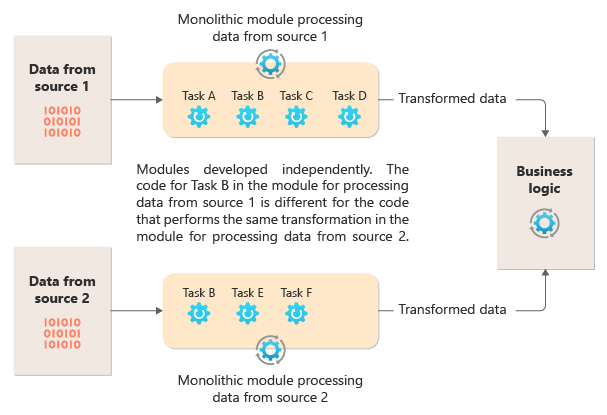
For instance, consider a data processing system where information needs to go through multiple stages of transformation, filtering, or enrichment. Without a modular structure, it becomes difficult to understand, modify, or extend the system. Pipes and Filters provide a solution by allowing each processing step to be encapsulated within a filter, and the data flows through interconnected pipes. This modular approach makes it easier to understand, maintain, and enhance the system over time. Additionally, filters can be reused in different contexts, promoting a more efficient and scalable design.
In summary, the “Pipes and Filters” architectural pattern addresses the challenges of managing complex processing tasks by breaking them into smaller, reusable components connected through channels. This promotes maintainability, scalability, and flexibility in designing software systems.
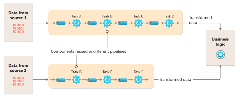
Break down the processing that’s required for each stream into a set of separate components (or filters), each performing a single task. To achieve a standard format of the data that each component receives and sends, the filters can be combined in the pipeline. Doing so avoids code duplication and makes it easy to remove or replace components, or integrate additional components, if the processing requirements change. This diagram shows a solution that’s implemented with pipes and filters:
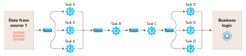
The time it takes to process a single request depends on the speed of the slowest filters in the pipeline. One or more filters could be bottlenecks, especially if a high number of requests appear in a stream from a particular data source. A key advantage of the pipeline structure is that it provides opportunities for running parallel instances of slow filters, which enables the system to spread the load and improve throughput.
The filters that make up a pipeline can run on different machines, which enables them to be scaled independently and take advantage of the elasticity that many cloud environments provide. A filter that’s computationally intensive can run on high-performance hardware, while other less-demanding filters can be hosted on less-expensive commodity hardware. The filters don’t even need to be in the same datacenter or geographic location, so each element in a pipeline to run in an environment that’s close to the resources it requires. This diagram shows an example applied to the pipeline for the data from Source 1:
If the input and output of a filter are structured as a stream, you can perform the processing for each filter in parallel. The first filter in the pipeline can start its work and output its results, which are passed directly to the next filter in the sequence before the first filter completes its work.
Another benefit of this model is the resiliency that it can provide. If a filter fails or the machine that it’s running on is no longer available, the pipeline can reschedule the work that the filter was doing and direct it to another instance of the component. Failure of a single filter doesn’t necessarily result in failure of the entire pipeline.
Using the Pipes and Filters pattern together with the Compensating Transaction pattern is an alternative approach to implementing distributed transactions. You can break a distributed transaction into separate, compensable tasks, each of which can be implemented via a filter that also implements the Compensating Transaction pattern. You can implement the filters in a pipeline as separate hosted tasks that run close to the data that they maintain.
Issues and considerations
Consider the following points when you decide how to implement this pattern:
-
Complexity. The increased flexibility that this pattern provides can also introduce complexity, especially if the filters in a pipeline are distributed across different servers.
-
Reliability. Use an infrastructure that ensures that data flowing between filters in a pipeline won’t be lost.
-
Idempotency. If a filter in a pipeline fails after receiving a message and the work is rescheduled to another instance of the filter, part of the work might already be complete. If the work updates some aspect of the global state (like information stored in a database), a single update could be repeated. A similar issue might occur if a filter fails after it posts its results to the next filter in the pipeline but before indicating that it’s completed its work successfully.
-
In these cases, the same work could be repeated by another instance of the filter, causing the same results to be posted twice. This scenario could result in subsequent filters in the pipeline processing the same data twice. Therefore, filters in a pipeline should be designed to be idempotent. For more information, see Idempotency Patterns on Jonathan Oliver’s blog.
-
Repeated messages. If a filter in a pipeline fails after it posts a message to the next stage of the pipeline, another instance of the filter might be run, and it would post a copy of the same message to the pipeline. This scenario could cause two instances of the same message to be passed to the next filter. To avoid this problem, the pipeline should detect and eliminate duplicate messages.
Note
If you implement the pipeline by using message queues (like Azure Service Bus queues), the message queuing infrastructure might provide automatic duplicate message detection and removal.
-
Context and state. In a pipeline, each filter essentially runs in isolation and shouldn’t make any assumptions about how it was invoked. Therefore, each filter should be provided with sufficient context to perform its work. This context could include a significant amount of state information.
Use this pattern when:
-
The processing required by an application can easily be broken down into a set of independent steps.
-
The processing steps performed by an application have different scalability requirements.
Note
You can group filters that should scale together in the same process. For more information, see the Compute Resource Consolidation pattern.
-
You require the flexibility to allow reordering of the processing steps that are performed by an application, or to allow the capability to add and remove steps.
-
The system can benefit from distributing the processing for steps across different servers.
-
You need a reliable solution that minimizes the effects of failure in a step while data is being processed.
This pattern might not be useful when:
-
The processing steps performed by an application aren’t independent, or they have to be performed together as part of a single transaction.
-
The amount of context or state information that’s required by a step makes this approach inefficient. You might be able to persist state information to a database, but don’t use this strategy if the extra load on the database causes excessive contention.
Example
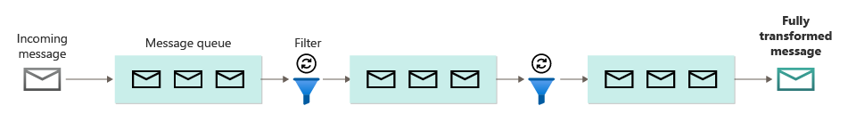
You can use a sequence of message queues to provide the infrastructure that’s required to implement a pipeline. An initial message queue receives unprocessed messages. A component that’s implemented as a filter task listens for a message on this queue, performs its work, and then posts the transformed message to the next queue in the sequence. Another filter task can listen for messages on this queue, process them, post the results to another queue, and so on, until the fully transformed data appears in the final message in the queue. This diagram illustrates a pipeline that uses message queues:
If you’re building a solution on Azure, you can use Service Bus queues to provide a reliable and scalable queuing mechanism. The ServiceBusPipeFilter class shown in the following C# code demonstrates how you can implement a filter that receives input messages from a queue, processes the messages, and posts the results to another queue.
Note
The ServiceBusPipeFilter class is defined in the PipesAndFilters.Shared project, which is available on GitHub.

Leave a Reply